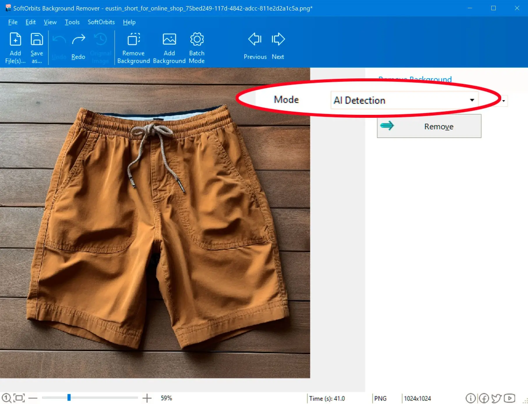
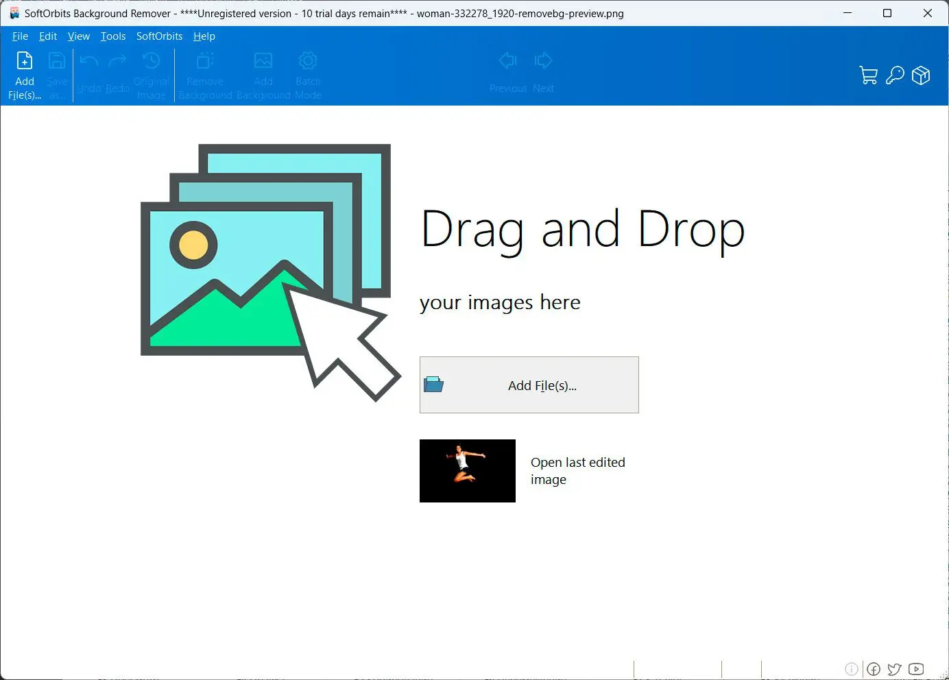
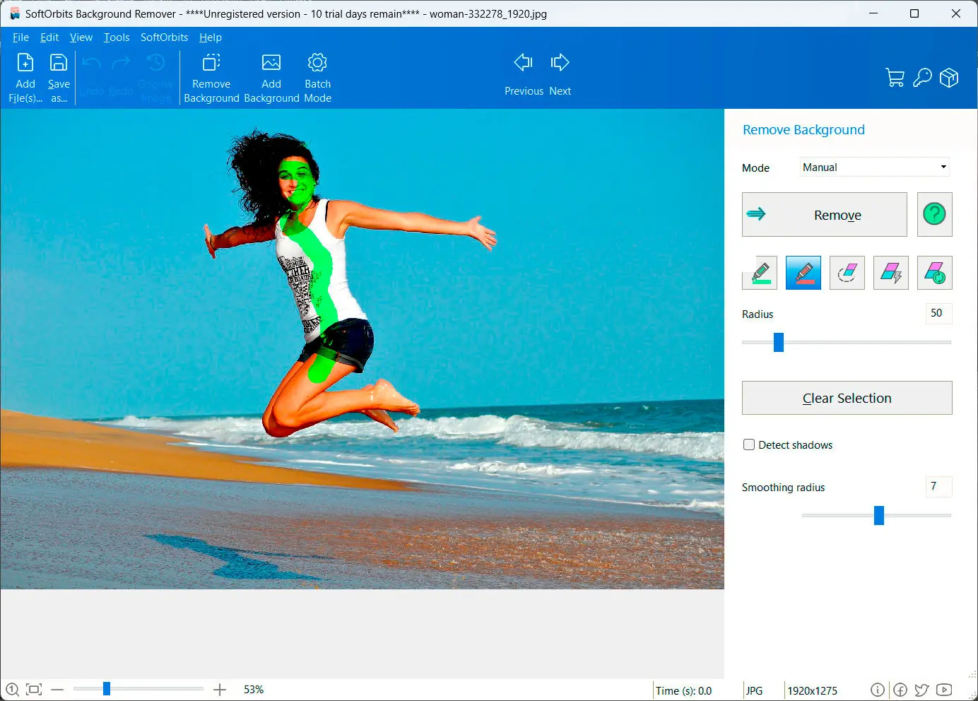
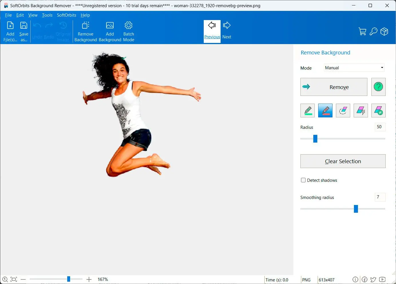
How to remove background from image: A Step-by-Step Guide
Recording Studio Wiring Diagram -
[AUDIO CABLE FLOW]
Prepared for: Studio Engineers, Installers, and Designers Date: April 17, 2026 Subject: Comprehensive guide to designing, reading, and implementing wiring diagrams for professional recording studios. 1. Executive Summary A recording studio’s wiring diagram is the blueprint of its nervous system. Unlike consumer audio setups, studios require balanced lines, star grounding, patchbay normalization, and multi-zone monitoring . Poor wiring introduces hum, crosstalk, and latency. This report details the three essential diagrams: Signal Flow , Patchbay , and Ground/Power Distribution . 2. Core Principles of Studio Wiring Before drawing any diagram, these rules must be understood:
Interface Main L Out → XLR M → Monitor Controller Input 1 Monitor Controller Out L → XLR F → Speaker L (Active) Monitor Controller Out R → XLR F → Speaker R Recording Studio Wiring Diagram
[ROOM DIAGRAM: Top View] [Wall AC] ---(dedicated 15A)--- [Furman PL-PRO DMC] ---+--- [Interface (USB powered from PC? No – external PSU)] | +--- [Mic Pre 1-8 rack] +--- [Headphone amp]
Mains Panel | |-- 20A Circuit (Analog): Preamp, EQ, Compressor, Console | (with isolated ground receptacle) | |-- 20A Circuit (Digital): Interface, Computer, Monitor controller, Digital reverb | (standard ground) | |-- 15A Circuit (Lighting, AC, Fridge) – separate from audio connect computer and monitor controller on the same power strip – the switching PSU of a computer injects noise into the ground. 6. Connector Pinout Reference Table (For Detail Diagram) Every wiring diagram must include a pinout legend. Here is the standard: or users will wire it backwards.
Mic (LDC) → XLR F→M → [Mic Pre 1 In] → TRS Out → Patchbay Top #1 (Half-normal) | +--- (normalled) → Patchbay Bottom #1 → Interface Input 1
| Principle | Requirement | |-----------|-------------| | | XLR (pin 2 hot, pin 3 cold, pin 1 shield) or TRS (tip hot, ring cold, sleeve shield). | | Impedance matching | Low-Z out (≤150Ω) to high-Z in (≥10kΩ) for mics; line-level out (600Ω) to line in (10kΩ). | | Star grounding | All chassis grounds connect to one central point (star) to eliminate ground loops. | | Signal separation | Never run AC power parallel to audio cables; cross at 90° if unavoidable. | | Color coding | Standard: Red = right/input, White = left/output, Black = ground, Yellow = word clock. | 3. Type 1: Signal Flow Diagram (High-Level) This is the conceptual map showing how audio moves from source to monitor. Typical Analog Signal Flow: Microphone → Preamp → Compressor (insert) → EQ (insert) → Line input on Interface/Console ↓ (via AUX send) → Reverb unit → Return to console ↓ Main L/R Out → Monitor Controller → Studio Monitors ↓ Also → Headphone amp (via cue mix) → Artist headphones Digital Signal Flow (Modern DAW-centric): Mic → Interface Pre (ADC) → USB/Thunderbolt → DAW (software) ↓ (internal routing) → (Via DAW) → Outboard compressor (via DAC → ADC loop) → Back to DAW ↓ DAC → Monitor Controller → Speakers ↓ Also → AES/EBU → Digital reverb → ADAT back to interface Key insight for diagram: Always draw direction arrows on every line. A complete diagram shows both XLR and TRS paths. 4. Type 2: Patchbay Wiring Diagram (The Heart of the Studio) The patchbay organizes connections without crawling behind racks. The diagram must specify normalling and top vs. bottom row assignment. 4.1 Normalling Types | Normalling | Symbol | Behavior | |------------|--------|----------| | Full Normal | FN | Top jack → Bottom jack automatically. Plugging into top or bottom breaks the internal connection. | | Half Normal | HN | Top jack → Bottom jack automatically. Plugging into top does not break bottom; plugging into bottom breaks top. (Used for mults/splits). | | Open (Non-Normal) | NN | No internal connection. Top and bottom are independent. | 4.2 Standard Patchbay Layout Example (48-point TT bay) Top Row (Outputs of gear) – Bottom Row (Inputs of gear) White = left/output
Insert cables (TRS to dual TS) – Tip = Send, Ring = Return. This must be explicitly drawn in a diagram, or users will wire it backwards. 7. Sample Wiring Diagram: Small Home Studio (Annotated) Below is a text-based representation of a complete wiring diagram for a 8-channel home studio.
| Connector | Pin | Signal (Balanced) | Color (Typical) | |-----------|-----|-------------------|------------------| | XLR Male/Female | 1 | Shield / Ground | Black | | | 2 | Hot (+) | Red | | | 3 | Cold (-) | White | | TRS ¼” | Tip | Hot (+) | Red | | | Ring | Cold (-) | White | | | Sleeve | Shield / Ground | Black | | TS (unbalanced) | Tip | Signal | Red | | | Sleeve | Ground | Black | | DB25 (Tascam pinout) | 1-8 | Shield | N/A – use numbered pins for channels 1-8 |
Interface Output 1 (DAW) → TRS → Patchbay Top #3 (Full-normal) | +--- (normalled) → Patchbay Bottom #3 → Compressor In | +-- Compressor Out → Patchbay Top #4 | +-- Patchbay Bottom #4 → Interface Input 3 (record processed)
 Photo Background Remover